为顶点程序提供顶点数据
Cg / HLSL顶点程序,必须通过顶点数据的结构。几个常用的顶点UnityCG中定义的结构。cginc包含文件,在大多数情况下,使用它们就足够了。的结构是:
appdata_base: vertex consists of position, normal and one texture coordinate.
appdata_tan: vertex consists of position, tangent, normal and one texture coordinate.
appdata_full: vertex consists of position, tangent, normal, four texture coordinates and color.
例如,这个材质颜色的网基于法线和只使用appdata_base顶点程序输入:
Shader "VertexInputSimple" {
  SubShader {
    Pass {
      CGPROGRAM
      #pragma vertex vert
      #pragma fragment frag
      #include "UnityCG.cginc"

      struct v2f {
          float4 pos : SV_POSITION;    //SV_Position描述像素的位置。可用在所有着色器0.5像素中心偏移量。
          fixed4 color : COLOR;
      };

      v2f vert (appdata_base v)
      {
          v2f o;
          o.pos = mul (UNITY_MATRIX_MVP, v.vertex);
          o.color.xyz = v.normal * 0.5 + 0.5;
          o.color.w = 1.0;
          return o;
      }

      fixed4 frag (v2f i) : SV_Target { return i.color; } //SV_Target 输出的值存储在一个渲染目标
      ENDCG
    }
  }
}
如果你想访问不同的顶点数据,你必须自己声明顶点结构,或者向顶点着色器添加输入参数。顶点数据是用CG / HLSL语义识别,必须从以下列表:
POSITION is the vertex position, typically a float4.
NORMAL is the vertex normal, typically a float3.
TEXCOORD0 is the first UV coordinate, typically a float2..float4.
TEXCOORD1 .. TEXCOORD3 are the 2nd..4th UV coordinates.
TANGENT is the tangent vector (used for normal mapping), typically a float4.
COLOR is the per-vertex color, typically a float4.
示例:
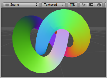
可视化UVs
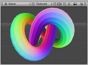
下面的例子使用的着色器顶点位置和第一纹理坐标顶点着色器输入(结构数据的定义)。这是非常有用的调试UV坐标的网格。UV坐标显示为红色和绿色的颜色,和0。1的范围之外的坐标有更多的蓝色色调应用。
    Shader "Debug/UV 1" {
        SubShader {
            Pass {
                Fog { Mode Off }
                CGPROGRAM

                #pragma vertex vert
                #pragma fragment frag

                // vertex input: position, UV
                struct appdata {
                    float4 vertex : POSITION;
                    float4 texcoord : TEXCOORD0;
                };

                struct v2f {
                    float4 pos : SV_POSITION;
                    float4 uv : TEXCOORD0;
                };

                v2f vert (appdata v) {
                    v2f o;
                    o.pos = mul( UNITY_MATRIX_MVP, v.vertex );
                    o.uv = float4( v.texcoord.xy, 0, 0 );
                    return o;
                }

                half4 frag( v2f i ) : SV_Target {
                    half4 c = frac( i.uv );
                    if (any(saturate(i.uv) - i.uv))
                        c.b = 0.5;
                    return c;
                }
                ENDCG
            }
        }
    }

Debug UV1 shader applied to a torus knot model
同样,这材质vizualizes第二UV集的模型:
    Shader "Debug/UV 2" {
        SubShader {
            Pass {
                Fog { Mode Off }
                CGPROGRAM

                #pragma vertex vert
                #pragma fragment frag

                // vertex input: position, second UV
                struct appdata {
                    float4 vertex : POSITION;
                    float4 texcoord1 : TEXCOORD1;
                };

                struct v2f {
                    float4 pos : SV_POSITION;
                    float4 uv : TEXCOORD0;
                };

                v2f vert (appdata v) {
                    v2f o;
                    o.pos = mul( UNITY_MATRIX_MVP, v.vertex );
                    o.uv = float4( v.texcoord1.xy, 0, 0 );
                    return o;
                }

                half4 frag( v2f i ) : SV_Target {
                    half4 c = frac( i.uv );
                    if (any(saturate(i.uv) - i.uv))
                        c.b = 0.5;
                    return c;
                }
                ENDCG
            }
        }
    }
可视化顶点颜色
以下着色器使用顶点位置和每个顶点的颜色作为顶点着色器的输入(结构数据的定义)。
    Shader "Debug/Vertex color" {
        SubShader {
            Pass {
                Fog { Mode Off }
                CGPROGRAM

                #pragma vertex vert
                #pragma fragment frag

                // vertex input: position, color
                struct appdata {
                    float4 vertex : POSITION;
                    fixed4 color : COLOR;
                };

                struct v2f {
                    float4 pos : SV_POSITION;
                    fixed4 color : COLOR;
                };

                v2f vert (appdata v) {
                    v2f o;
                    o.pos = mul( UNITY_MATRIX_MVP, v.vertex );
                    o.color = v.color;
                    return o;
                }

                fixed4 frag (v2f i) : SV_Target { return i.color; }
                ENDCG
            }
        }
    }

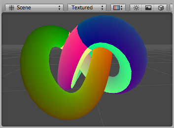
可视化法线
以下着色器使用顶点位置和法线作为顶点着色器的输入(结构数据的定义)。正常的X,Y,Z组件可视为R,G,B颜色。因为正常的组件是在–1。1的范围内,我们的尺度和偏差,输出的颜色都在显示0。1范围。
```javascript
Shader "Debug/Normals" {
    SubShader {
        Pass {
            Fog { Mode Off }

            CGPROGRAM
            #pragma vertex vert
            #pragma fragment frag

            // vertex input: position, normal
            struct appdata {
                float4 vertex : POSITION;
                float3 normal : NORMAL;
            };

            struct v2f {
                float4 pos : SV_POSITION;
                fixed4 color : COLOR;
            };

            v2f vert (appdata v) {
                v2f o;
                o.pos = mul( UNITY_MATRIX_MVP, v.vertex );
                o.color.xyz = v.normal * 0.5 + 0.5;
                o.color.w = 1.0;
                return o;
            }

            fixed4 frag (v2f i) : SV_Target { return i.color; }
            ENDCG
        }
    }
}
```
调试法线材质应用到一个模型。您可以看到模型硬阴影边缘。
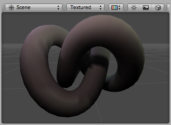
可视化切线和副法线
切线和副法线向量用于法线贴图。在Unity只有切向量存储在顶点,和副法线来源于正常和切。
The following shader uses vertex position and tangent as vertex shader input (defined in structure appdata). Tangent’s X,Y,Z components are visualized as R,G,B colors. Because the normal components are in –1..1 range, we scale and bias them so that the output colors are in displayable 0..1 range. 以下材质使用顶点位置和切作为顶点着色器输入(在结构appdata定义)。切的X,Y,Z组件可视化为R,G,B的颜色。因为正常的组件在-1 . .1范围内,我们的规模和偏见,这样输出颜色是可显示的0 . .1范围。
Shader "Debug/Tangents" { SubShader { Pass { Fog { Mode Off } CGPROGRAM
    #pragma vertex vert
    #pragma fragment frag

    // vertex input: position, tangent
    struct appdata {
        float4 vertex : POSITION;
        float4 tangent : TANGENT;
    };

    struct v2f {
        float4 pos : SV_POSITION;
        fixed4 color : COLOR;
    };

    v2f vert (appdata v) {
        v2f o;
        o.pos = mul( UNITY_MATRIX_MVP, v.vertex );
        o.color = v.tangent * 0.5 + 0.5;
        return o;
    }

    fixed4 frag (v2f i) : SV_Target { return i.color; }
    ENDCG
}
} }
调试切线材质应用到一个模型。
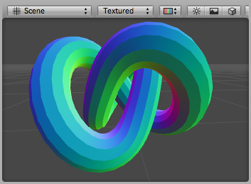
The following shader visualizes binormals. It uses vertex position, normal and tangent as vertex input. Binormal is calculated from normal and tangent. Just like normal or tangent, it needs to be scaled and biased into a displayable 0..1 range. 以下材质可视化副法线。它使用顶点位置,正常和切顶点输入。从正常和切副法线计算。就像正常或切线,它需要扩展和偏见到一个可显示的0 . .1范围。
Shader "Debug/Binormals" { SubShader { Pass { Fog { Mode Off } CGPROGRAM
    #pragma vertex vert
    #pragma fragment frag

    // vertex input: position, normal, tangent
    struct appdata {
        float4 vertex : POSITION;
        float3 normal : NORMAL;
        float4 tangent : TANGENT;
    };

    struct v2f {
        float4 pos : SV_POSITION;
        float4 color : COLOR;
    };

    v2f vert (appdata v) {
        v2f o;
        o.pos = mul( UNITY_MATRIX_MVP, v.vertex );
        // calculate binormal
        float3 binormal = cross( v.normal, v.tangent.xyz ) * v.tangent.w;
        o.color.xyz = binormal * 0.5 + 0.5;
        o.color.w = 1.0;
        return o;
    }

    fixed4 frag (v2f i) : SV_Target { return i.color; }
    ENDCG
}
} }
调试副法线材质应用到一个模型。漂亮!